
Electroplating
In metal electrodeposition, the workpiece on the carrier rail is the cathode (−) and the counter-electrode is the anode (+). ERKO contact blocks can be used at the carrier rail and to connect the anode side.
ERKO · High-current contact systems
ERKO contact blocks transfer current to the carrier rail. Contact heads connect racks electrically to the rail. We adapt the design and connections to your electroplating, anodising or printed circuit board production line.
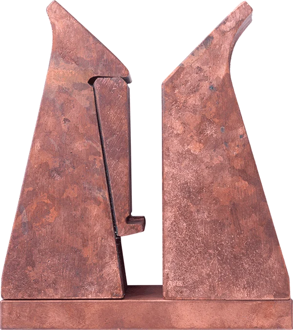
Contact blocks establish the electrical connection to the carrier rail. This section covers only the E, K, D, K-D, D-R and K-D-R contact block designs.
The current rating is confirmed for each design. This range does not apply to every type or to contact heads.
Inserting the carrier rail pushes the moving contact wedge down and establishes contact. Lifting the rail releases the connection. No separate clamping actuator is needed.
ERKO contact blocks are used in nickel, copper, zinc and chromium processes, anodising and hard anodising, and PCB production. We match the design, required current and connections to the particular production line.
In metal electrodeposition, the workpiece on the carrier rail is the cathode (−) and the counter-electrode is the anode (+). ERKO contact blocks can be used at the carrier rail and to connect the anode side.
During anodising, the aluminium workpiece on the carrier rail is the anode (+) and the counter-electrode is the cathode (−). Contact systems can be configured for either electrode side.
ERKO contact blocks are also used in printed circuit board production. Rail dimensions, installation space and electrical connections are agreed for the specific line.
A single contact block, supplied separately or on a base plate.
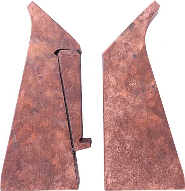
Without base plate. Consider the existing support and mounting when selecting a design.
With base plate for mounting. Connection and fastening are adapted to the installation.
Double contact block with two moving contact wedges.
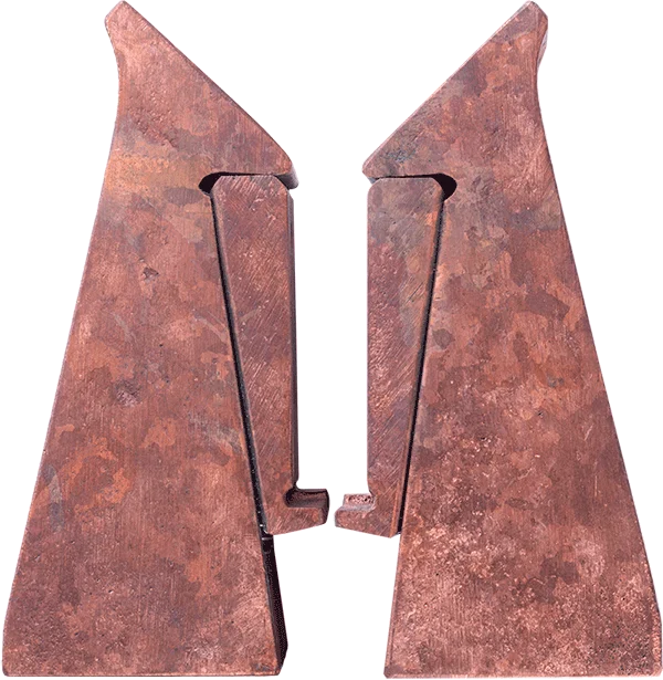
Without base plate. Consider the existing support and mounting when selecting a design.
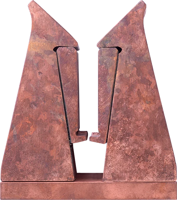
With base plate for mounting. Connection and fastening are adapted to the installation.
Round design of the double contact block.
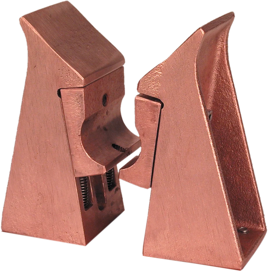
Without base plate. Consider the existing support and mounting when selecting a design.
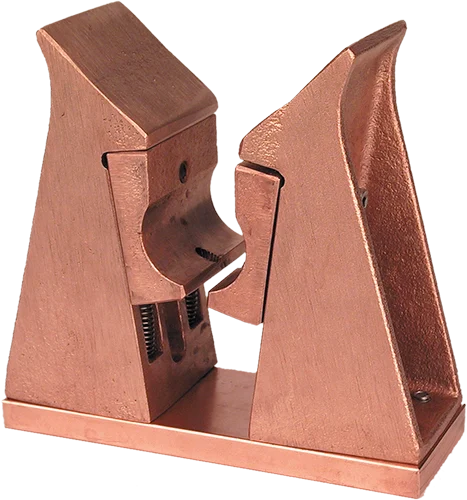
With base plate for mounting. Connection and fastening are adapted to the installation.
The overall range of 250 to 10,000 A applies to the product family. Current rating, installation dimensions and suitable design are assessed separately for each enquiry.
The contact surfaces are machined to produce flat surfaces for electrical contact and current transfer. Robust cast construction, self-clamping operation and a simple mechanical design characterise the contact blocks.
In the 1980s, we cast the blanks in-house. Today, the cast blanks are produced externally; Erhardt ERKO carries out the CNC machining of the copper-chromium cast blanks.
The existing technical drawings show rail dimensions relevant to your enquiry. They do not replace an approved installation drawing for the specific design.
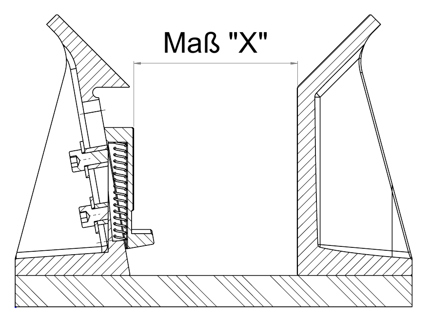
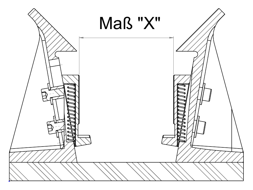
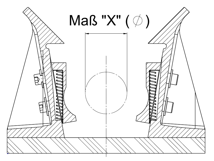
Base plates can have straight or angled connection lugs and adapted mounting arrangements. Erhardt ERKO CNC-machines the copper-chromium cast blanks. We agree mechanical and electrical interfaces for your equipment.
Start with the required current and rail shape. Then agree the base plate, fastening and rectifier connection. The table identifies the designs; it does not replace project-specific sizing.
The contact block size is generally selected according to the customer’s rectifier. A typical example is a 3,000 A contact block for a 3,000 A rectifier. We confirm the appropriate design together with the rail shape, fastening and electrical connections.
| Type | Design | Base plate |
|---|---|---|
| E | Single | Without |
| K | Single | With |
| D | Double | Without |
| K-D | Double | With |
| D-R | Round double | Without |
| K-D-R | Round double | With |
Single contact blocks are the most commonly used designs. Whether a base plate is required depends on the installation.
Double contact blocks are an option where carrier rails have different widths. We agree the required design with you.
Round designs are intended for barrel electroplating lines. The rail diameter and connection determine the specific adaptation.
Confirm for each type: current rating, permitted rail dimensions, installation dimensions, fastening and electrical connections. The existing sketches are reference illustrations, not approved installation drawings.
The current you need and details of the production line.
Shape, width or diameter X, and a dimensioned drawing or photograph.
Available space, existing fastening, base plate and rectifier connection.
Preferred type, quantity and photographs of existing parts for a replacement.
We adapt ERKO contact blocks to your carrier rail. For custom designs, photographs, hand sketches and dimension X of the relevant rail are helpful. We normally prepare a drawing of the custom part to plan a suitable replacement.
Existing contact blocks from other manufacturers can be replaced with suitably adapted, complete ERKO contact blocks. Fastening and electrical connections can be adapted in most cases. We prepare and discuss the necessary sketches and drawings with you. We do not supply spare parts for other manufacturers’ products.
Dimensions are available in the existing PDF documents. Drawings for the agreed design are available on request, since customers’ carrier rails and installation arrangements differ.
Maintenance includes occasionally lubricating the wedge slider with copper paste. Springs can be replaced when needed. Customers can carry out maintenance and part replacement themselves.
We can supply replacements for every individual component of our ERKO contact blocks. Tell us the existing type and the part required; photographs help identify the component.
We still receive replacement enquiries from customers who purchased their ERKO contact blocks in the 1980s.
You can order from one unit, including customised designs.
We stock many sizes. Availability and the delivery date are confirmed for your enquiry.
Most of our customers are in the European Union. We have also supplied customers in Brazil and Canada.
These older documents contain historical company details, type names and some different current ratings. The current designation for the single contact block with base plate is K; historical documents also use K-E. Use the current selection guide and the confirmation for your project.
No. It is the confirmed range for the contact block family. The rating for the selected type is established for your enquiry.
In the existing K and K-D sketches, X denotes the relevant carrier rail width. In the K-D-R sketch, X is the diameter of the round carrier rail. Please also specify the rail shape and installation arrangement.
This depends on the existing fastening and connection. E, D and D-R are described without a base plate; K, K-D and K-D-R with one. We agree the specific mounting with you.
The described contact block principle is self-clamping: inserting and loading the rail establishes contact; lifting it releases the contact. No separate actuator is required for this clamping operation.
The sketches show relevant dimensions but do not replace an approved installation drawing. Current rating, dimensions, fastening and electrical connections must be confirmed for the selected product.
Contact heads connect the rack electrically to the carrier rail. The KK and FK designs differ in construction and handling.
Contact heads establish the electrical connection between rack and carrier rail. Current rating, rail width X and installation arrangement determine the selection.
The cast KK contact head grips the carrier rail through a self-clamping wedge mechanism. The technical documentation describes releasing the clamp with a hand lever placed between the rail and the lug provided on the contact head; counter-pressure is also described as an alternative.
The FK contact head has a simpler construction. A spring-loaded clamping plate presses the carrier rail against the contact surface. The head is easier to remove from the rail again. The design is matched to the individual rail width.
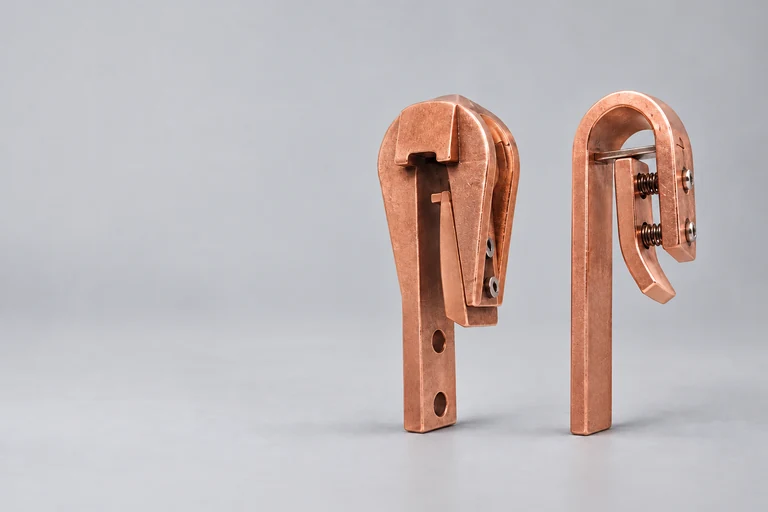
Contact heads slide onto the carrier rail from above. The rack is attached by bolted connections. You can provide the required holes and threads yourself, or arrange for ERKO to machine them.
We agree the appropriate contact head design with you based on the required current, carrier rail width and rack attachment.
The older data sheet describes KK and FK contact heads. Company details and technical information reflect the earlier version; we agree the appropriate current design with you.
Tell us which product group you need and, if known, the type. For either group, include the required current, relevant rail dimensions, installation details and quantity. Photographs or drawings help complete your enquiry.
Use the shared accessory selection. It shows the current status of enquiry delivery and our direct contact details. Include the required current, rail dimensions, quantity and photographs or drawings.
The selection guide includes an overview of contact block designs, information on KK/FK contact heads and an enquiry checklist. Binding ratings and drawings are agreed for the selected product.
Tell us the required current, rail dimensions and installation arrangement. The accessories overview leads to the shared enquiry and our contact details.
Enquire about a suitable contact system