Adapt the fixture to your component
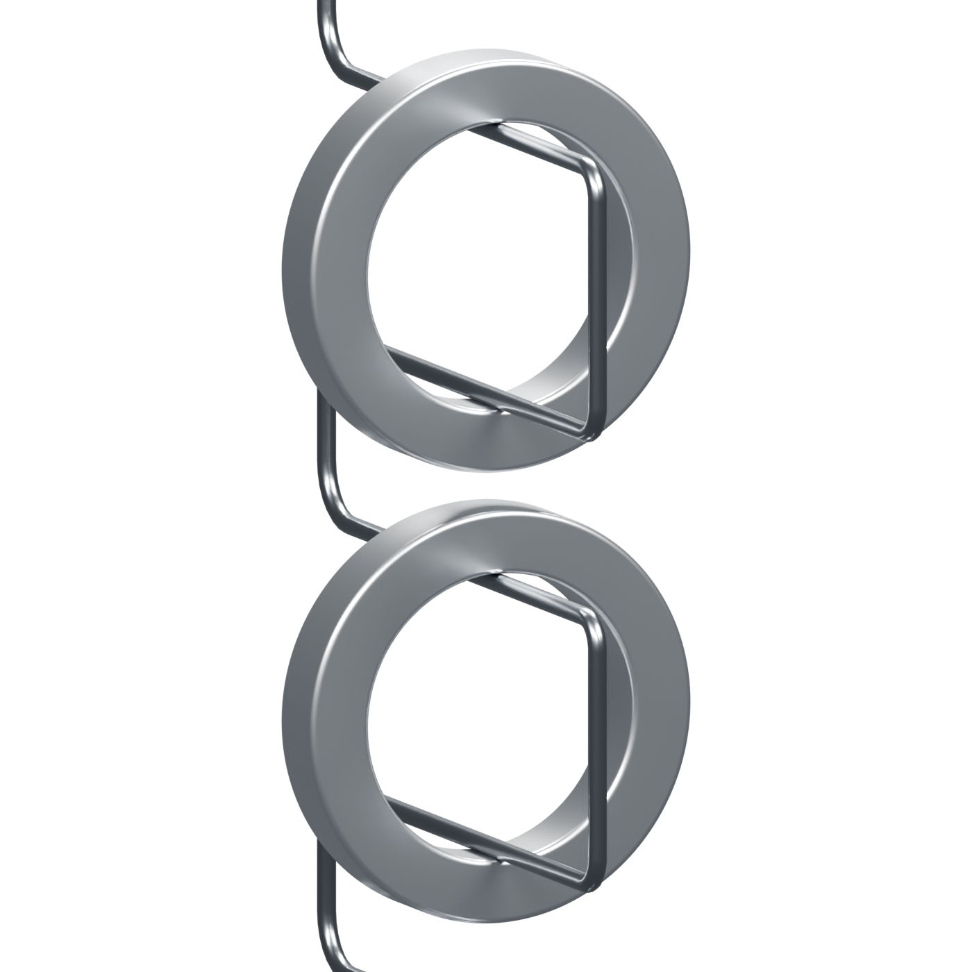
Component-specific jigs fit particular geometries and take up floor or storage space. The wire fixture can be matched to your component, which is then electrically contacted on a standard frame.
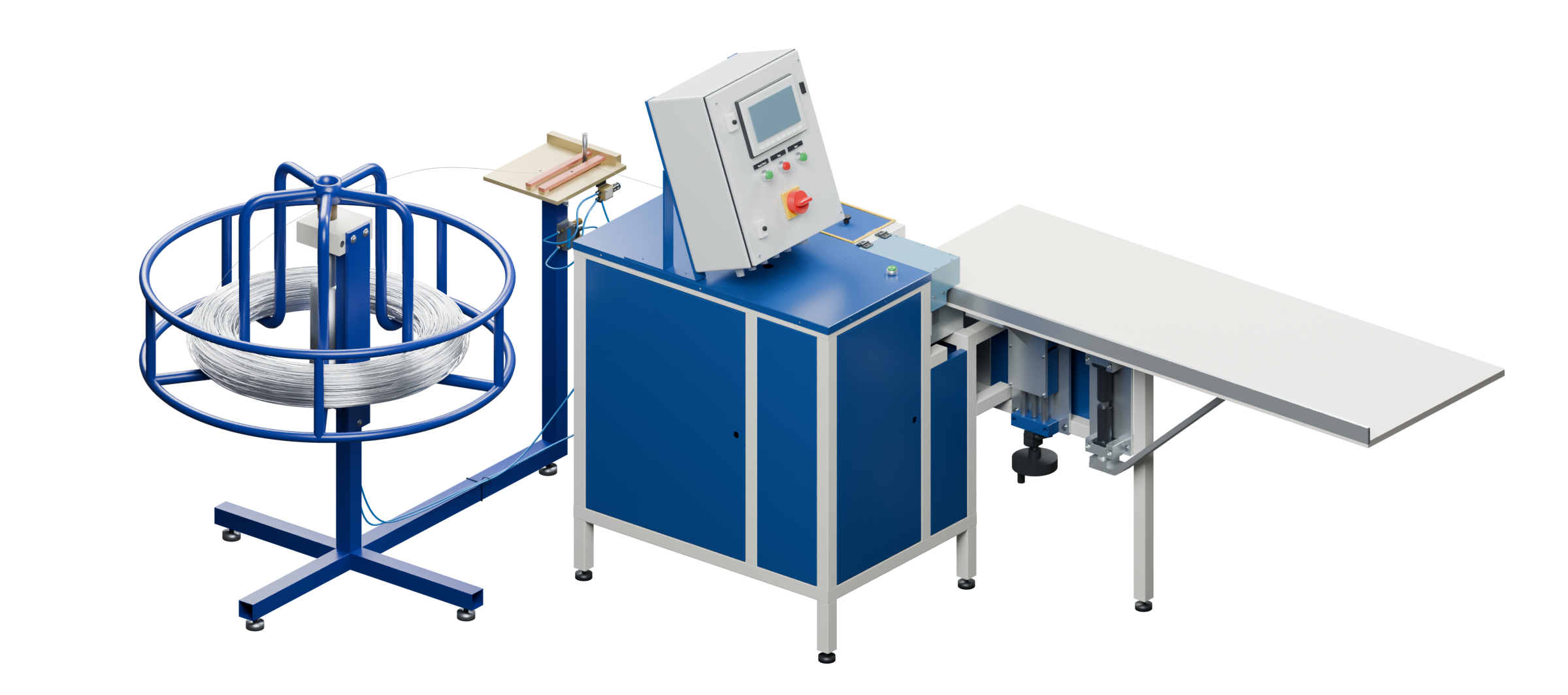 ERKO Staffelautomat with wire reel ↗
The right fixture for your components – for efficient loading and electrical contact during anodising.
Make your own wire fixtures.
The ERKO Staffelautomat makes it possible.
New components to process.
How do we make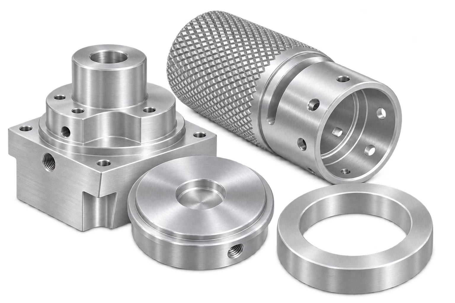
Geometry & mounting points
Make suitable wire fixtures yourself
Then anodise in your own plant
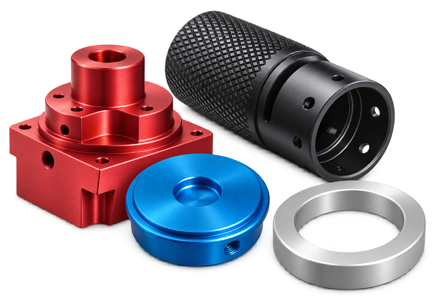
Unload · red, blue, black, natural
Component-specific jigs fit particular geometries and take up floor or storage space. The wire fixture can be matched to your component, which is then electrically contacted on a standard frame.
Enter the loop count, spacing, start and end lengths, and the number of wires in the program.
Components contacted using aluminium wire can also be electrolytically coloured in these shades.
From the hole to electrical contact
Scroll through three applications – from fitting the first component to the loaded frame.
Explore the contact process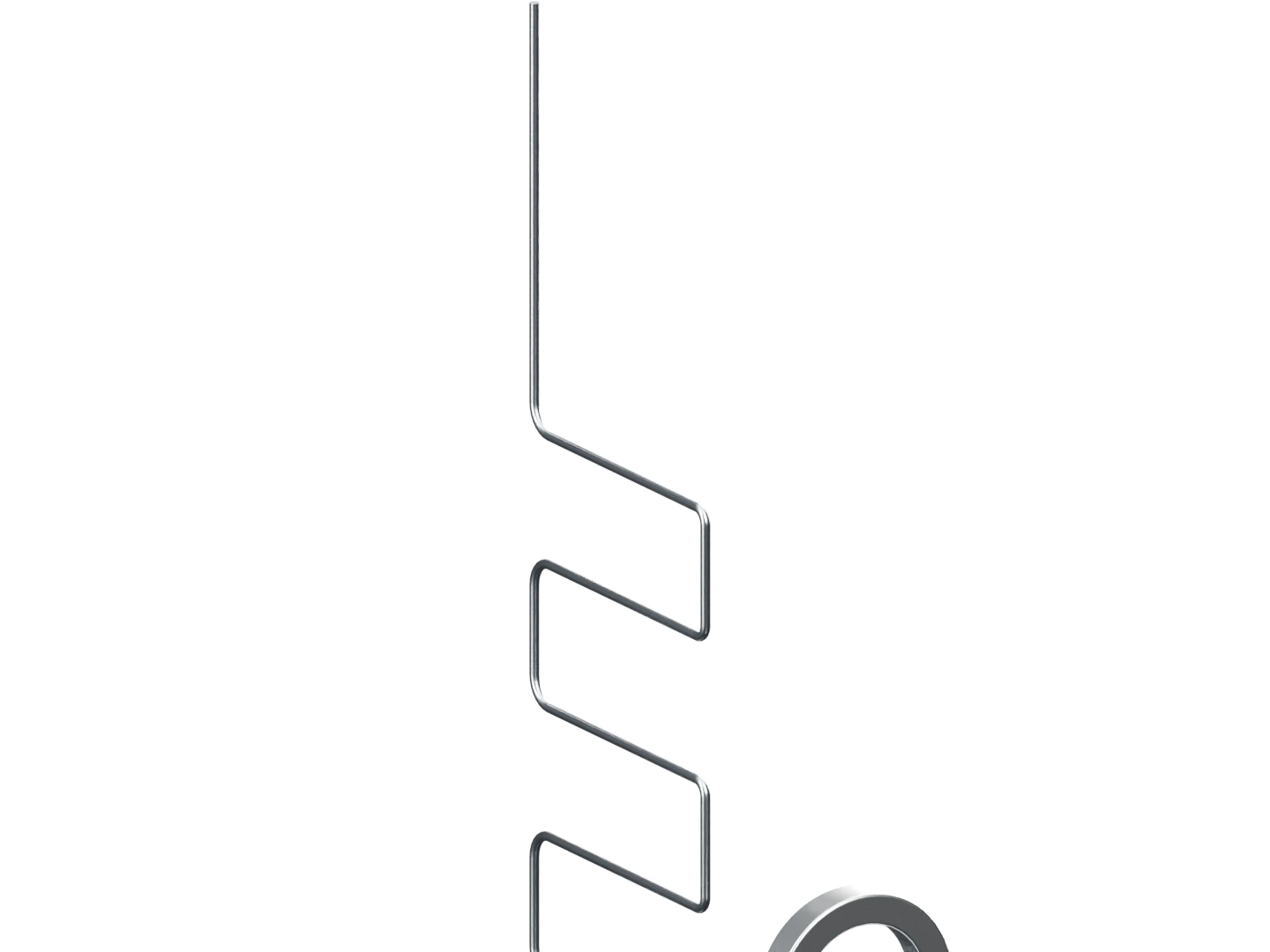
Align the hole. Fit the component onto the loop.
Loading the view …
Applications at a glance
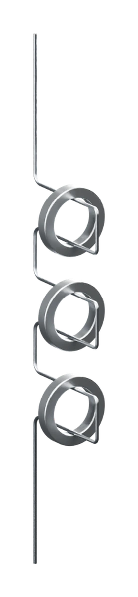
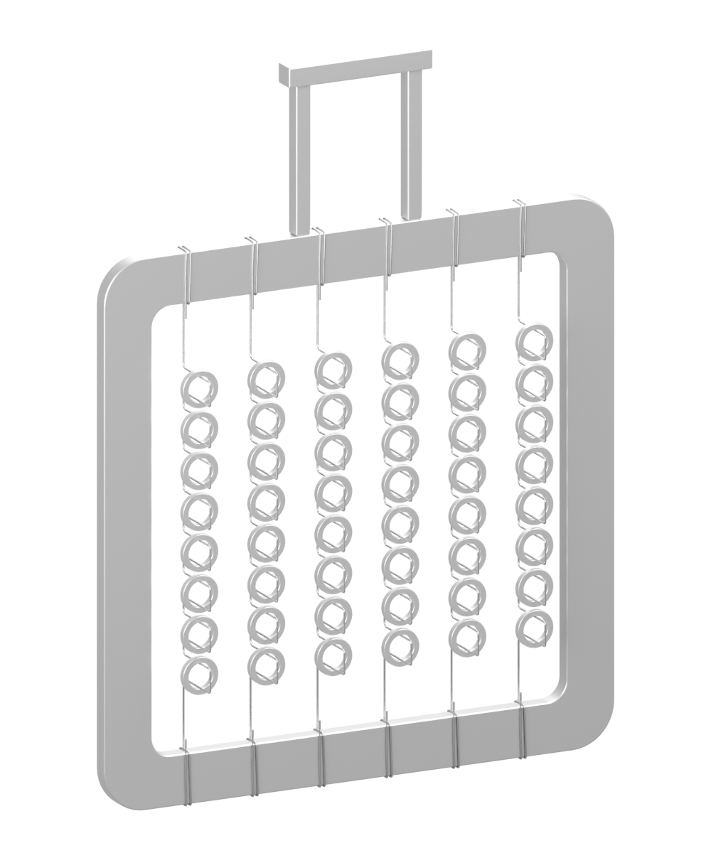
One wire with several loops holds the components one after another.
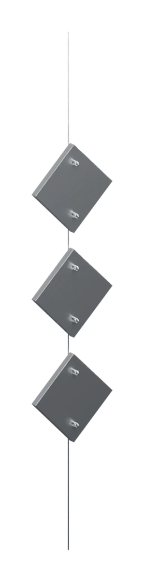
Two loops form the fixture for one component.
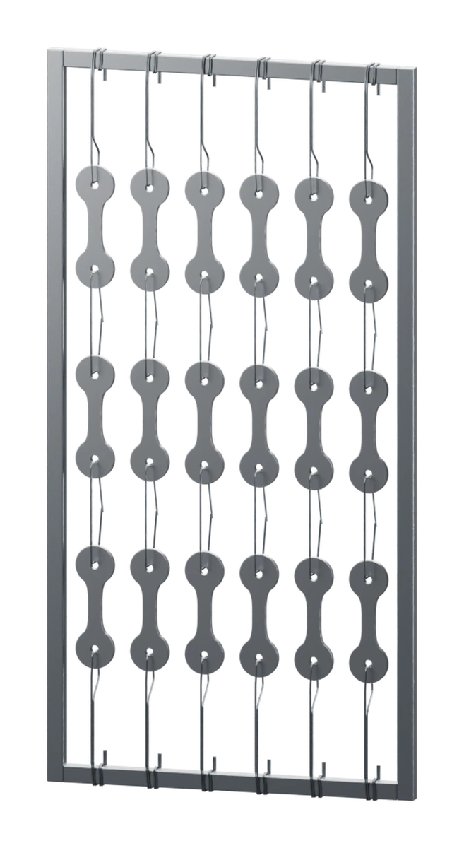
The loaded wire is secured to the top and bottom of the frame.
The number and arrangement are examples. The right fixture depends on your component and frame loading.
From wire to fixture
The reel supplies the wire. The ERKO Staffelautomat forms it into the right fixture for your components.
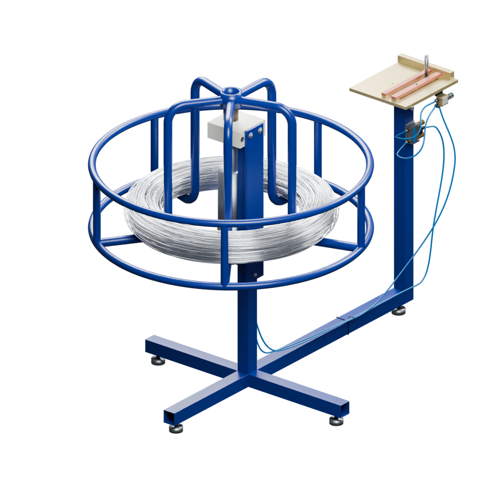
01 · Supplying the wire
It holds the wire supply and pneumatically feeds more material when the wire is pulled. This supplies the wire for processing in the ERKO Staffelautomat.
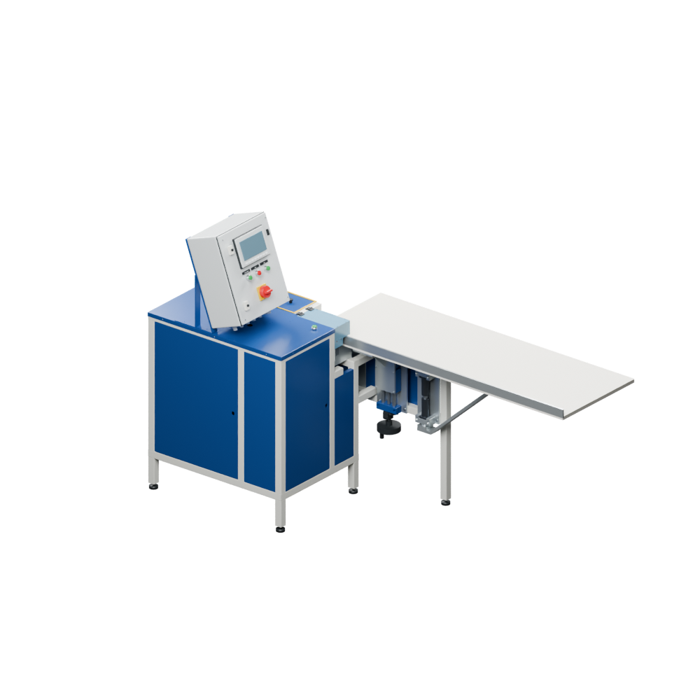
02 · Forming the wire
Feed, bend and cut to length: the machine produces loops, paired loops, C-hooks and straight wire lengths. Enter the required dimensions on the Siemens touch panel.
See it in the filmFrom wire to component fixture
From wire to the right fixture – an explanatory film about the machine and its applications.
The number of loops shown is an application example. The number and arrangement depend on your component and frame loading.
Choose a wire form. Its application and the corresponding control-panel view are shown side by side.
Fit components with a suitable hole onto the preformed loop.
The ERKO Staffelautomat produces wire forms and cut lengths. Fitting, bending, wrapping and tensioning are carried out afterwards when loading the frame.
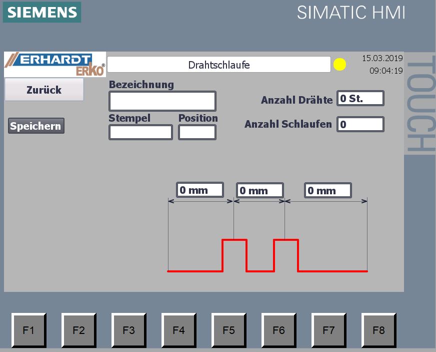
Hold larger components at two equally sized holes at the same time. Both loops in a pair are the same size.
The ERKO Staffelautomat produces wire forms and cut lengths. Fitting, bending, wrapping and tensioning are carried out afterwards when loading the frame.
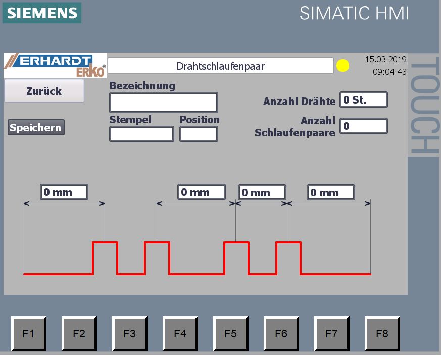
Connect adjacent components. After threading, the free hook ends are bent over or pressed closed slightly.
The ERKO Staffelautomat produces wire forms and cut lengths. Fitting, bending, wrapping and tensioning are carried out afterwards when loading the frame.
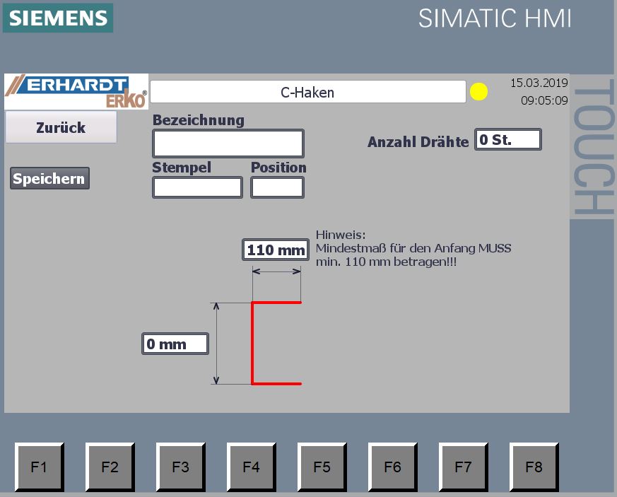
To secure the wire to the frame, pre-bend it by hand, thread it through and wrap both ends together around the frame profile.
The ERKO Staffelautomat produces wire forms and cut lengths. Fitting, bending, wrapping and tensioning are carried out afterwards when loading the frame.
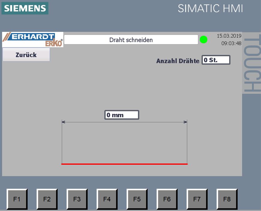
The Siemens SIMATIC HMI images show the inputs for loops, paired loops, C-hooks and straight wire lengths. The values shown belong to the documented control-panel version from 2019; we will discuss the current version with you.
Original photographs
Wire forms and contacting in practice. Select an example to view the photograph in detail.
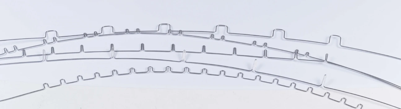
Different loop forms and spacings: the wire fixture is matched to the mounting points on the component.
The photographs show application examples. Wire form, number of loops and frame loading depend on the component.
Setup & application
From the mounting point on your component to the right wire for your frame: you specify the wire form, dimensions and quantity for your application.
The machine forms and cuts aluminium wire to hold components during anodising: single loops, double loops, C-hooks or straight wire lengths. Your component is the starting point: where can it be held, and which hole or contact point is available?
The selected forming die determines the wire form. Choose the die to suit the mounting point on the component and enter the required dimensions in the program: the number of loops, spacing within and between loops or loop pairs, and the start and end lengths. This adapts the wire to the component spacing and subsequent tensioning on your frame.
You also enter the number of wires to produce. For example, if one wire holds ten components and you produce one hundred wires, you have planned capacity for 1,000 components. Component spacing and frame loading must suit your application; the example is not a fixed machine capacity.
The finished wire forms are then loaded with components by hand and secured, electrically contacted or tensioned on the frame. Fitting, bending, wrapping and tensioning are part of this subsequent loading process.
For high-volume components, we can assess a special configuration on request in which the loop is formed directly in the component or the parts are placed directly onto the loops. This requires a suitable height-adjustable table. The exact process, suitable applications and technical limits are subject to project-specific clarification.
Our origins: our own anodising operation in Buchen.
Developed to make electrical contact with components in our own operation.
A simple CNC system supplements the proven machine principle.
New control system and a thoroughly redesigned housing.
As of November 2026: four machines nearing completion. Configuration and availability on request.